
At Stedmans Garage, we specialise in diagnosing and repairing common issues in Mini Cooper vehicles, including no-start and no-crank conditions. This blog post outlines the diagnostic process we followed to identify and resolve a specific issue with a Mini Cooper that exhibited these symptoms. We will detail the steps taken, the components involved, and the solutions implemented to ensure the vehicle operates reliably once again.
Initial Diagnosis
Upon arrival, the customer reported that the engine would not start. To begin our diagnosis, we connected a battery maintainer to the car. This was essential to ensure the vehicle's voltage remained stable during our extended testing, avoiding discrepancies that could lead to misdiagnosis.
As we attempted to start the vehicle, dashboard lights illuminated, but the engine remained unresponsive. A prompt indicating "put foot down on the clutch" appeared, a common requirement for Mini and BMW models. This light turns off when the clutch is engaged, signalling that the car is ready to start.
Checking the Basics
The first step in diagnosing any no-start condition is to check the battery. A healthy battery is crucial for starting any vehicle, and we employed a battery tester that indicated the battery was "BAD & REPLACE." Even after testing with an alternative battery, the no-start condition persisted. We advised the customer that, regardless of the outcome of our diagnostics, they should consider replacing the aged battery as a precaution.
Diagnostic Tools Utilised
For the diagnostic process, we used the Autologic Drive PRO, a sophisticated tool designed to read fault codes and provide real-time data. This tool is vital in modern automotive diagnostics, allowing us to pinpoint issues effectively.
Fault Codes Logged
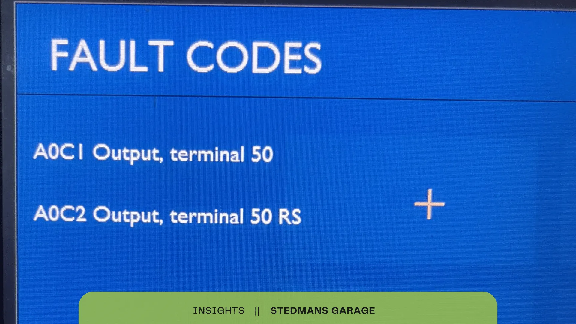
During our initial diagnostics, we noted two fault codes:
- A0C1: Output, terminal 50
- A0C2: Output, terminal 50 RS
These codes indicated an issue with terminal 50, which is responsible for sending the starter signal. The main cable connects to the starter, and a secondary lead goes to the solenoid, commanding the starter motor to engage. Understanding these fault codes is essential as they direct our attention to specific components that require inspection.
Live Data Analysis
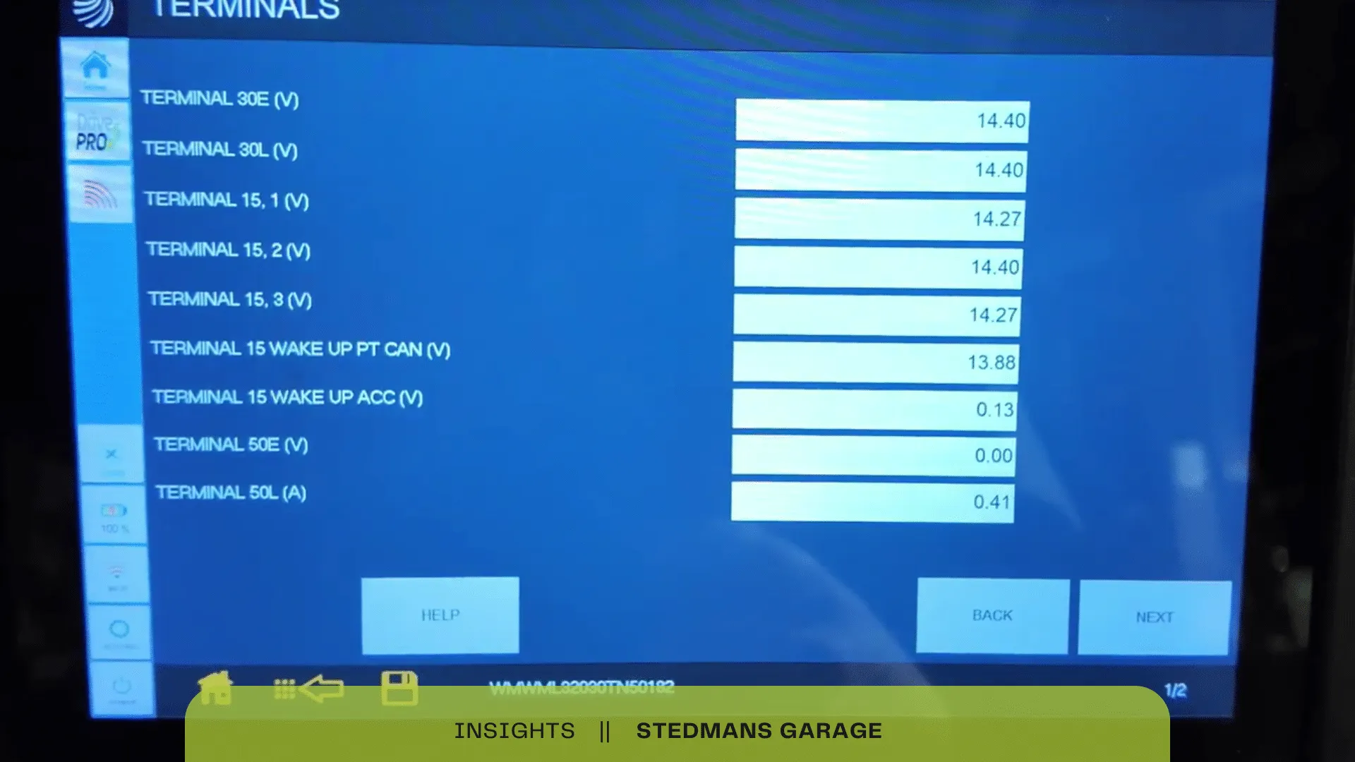
Next, we examined the CAS (Car Access System) module to request live data. Looking specifically at terminal 50, we checked the voltage and amperage:
- Voltage: 0.00 V
- Amperage: 0.41 A
The absence of voltage (0.00 V) while attempting to start the vehicle, even with the clutch pedal depressed, indicated a problem with the signal being sent to the starter motor. This is a critical step in diagnostics, as live data often reveals issues that fault codes may not.
Clutch Switch Inspection
Utilising our diagnostic tools, we assessed the clutch switch, which indicated it was "not depressed," even when the clutch pedal was pressed. For the Mini Cooper to start, the system must detect that the clutch has been engaged; otherwise, the starter will not activate. This safety feature is crucial to prevent unintended vehicle movement.
Investigating the Clutch Position Sensor
To delve deeper, we focused on the clutch pedal position sensor, which we identified as a hall effect sensor equipped with four wires. Hall effect sensors are commonly used in automotive applications, such as:
- Clutch Position Sensors: Detects the position of the clutch pedal.
- Accelerator Pedals: Monitors throttle position for engine control.
- Camshaft and Crankshaft Position Sensors: Essential for engine timing and operation.
Wiring Diagram Review
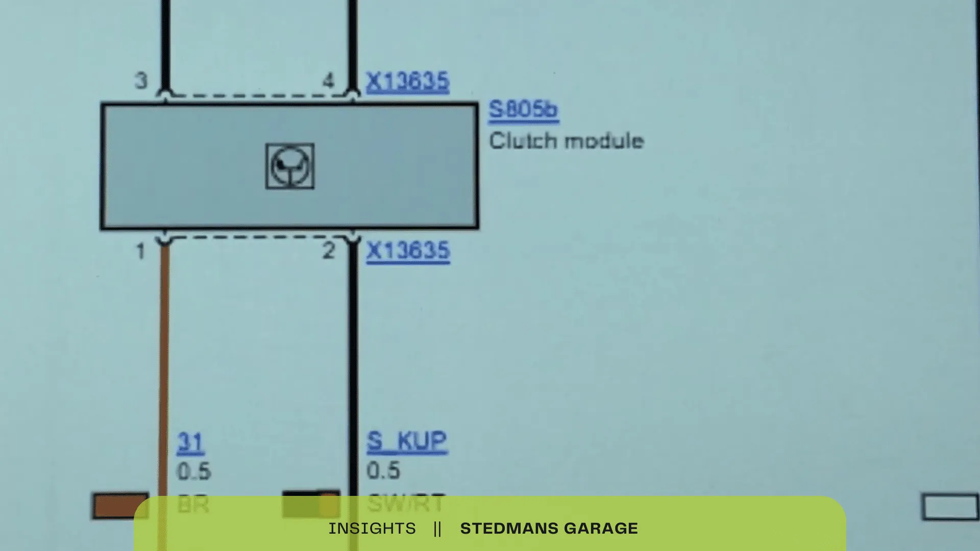
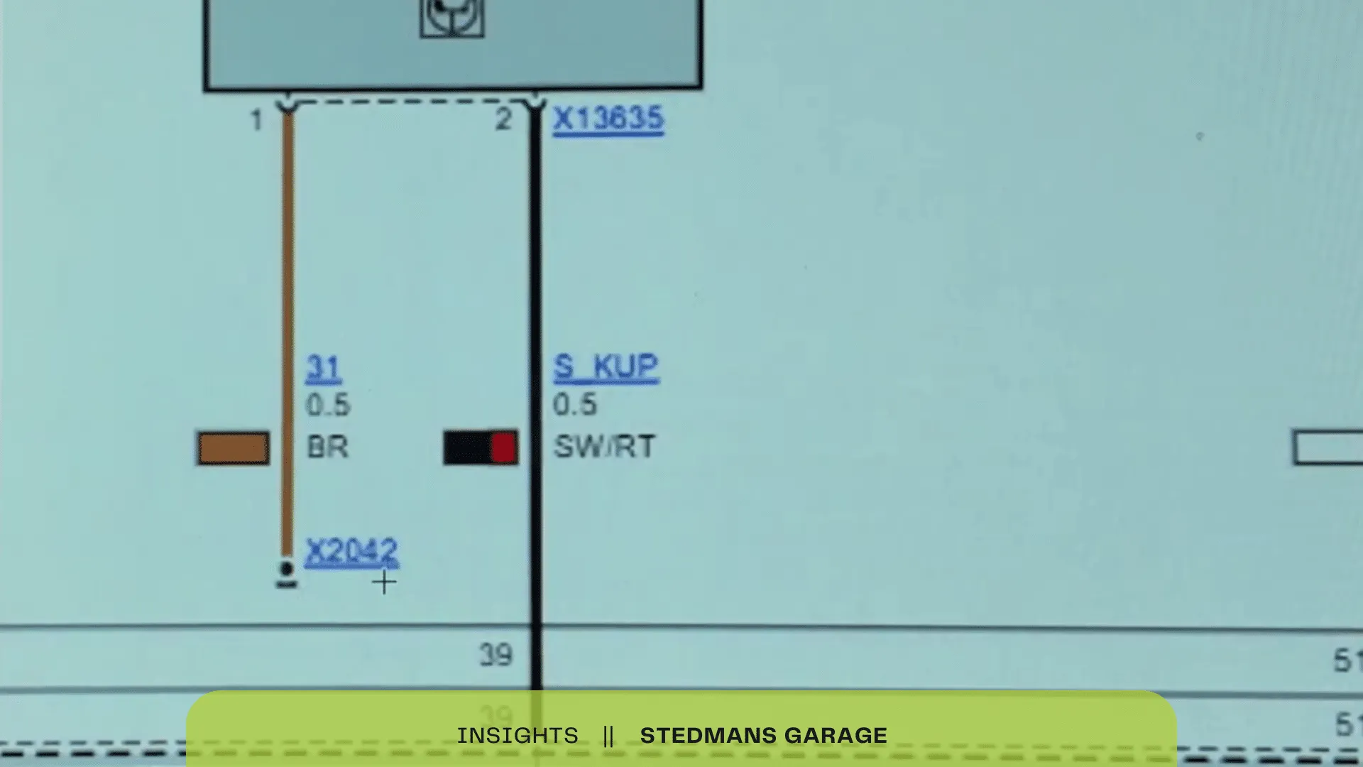
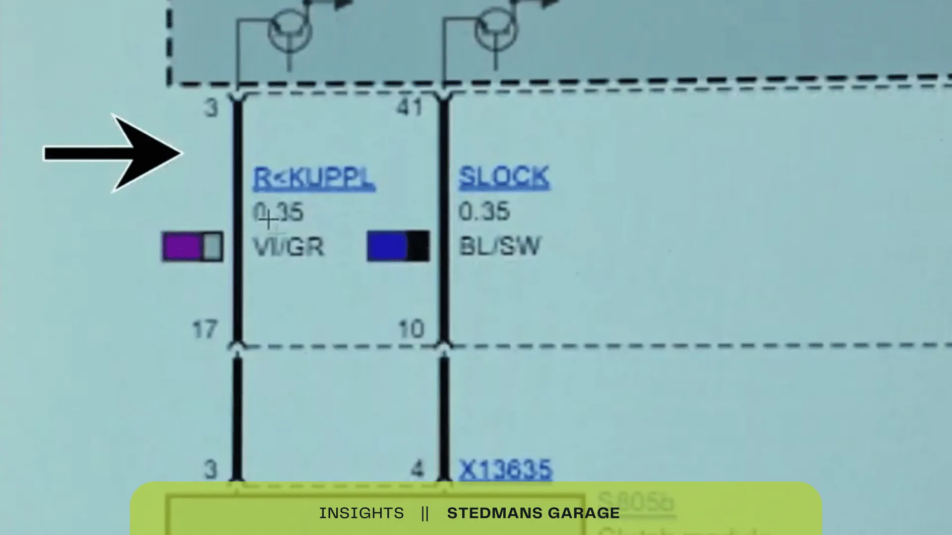
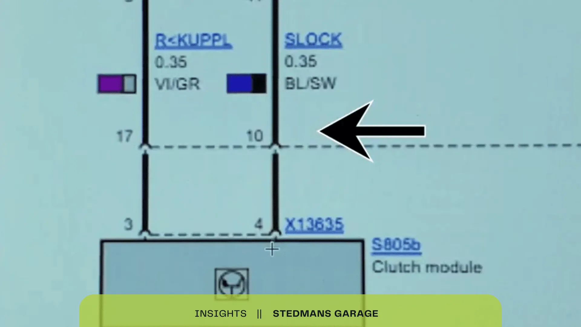
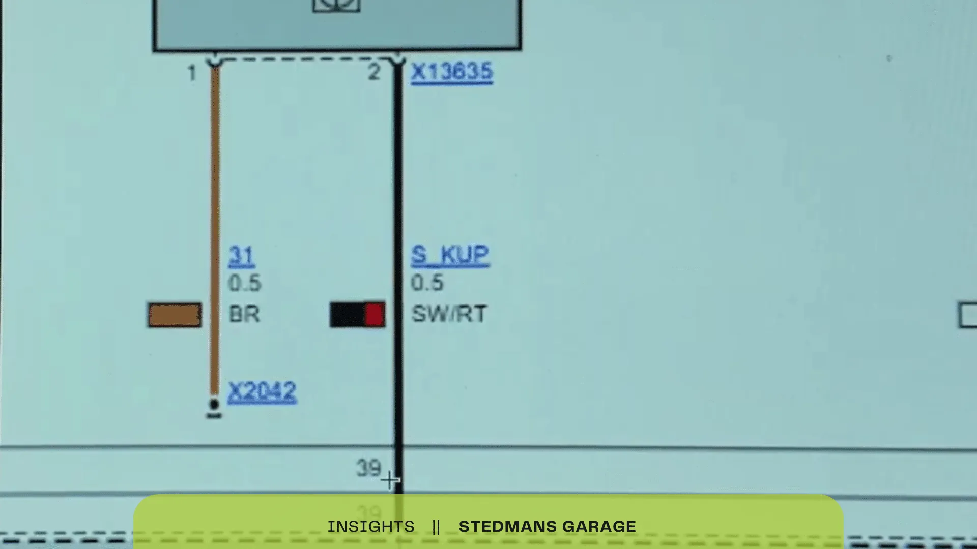
According to the wiring diagram, here’s how the wiring is configured:
- Pin 1 (orange wire): Ground
- Pin 3 (purple wire): Power supply to the hall effect sensor
- Pin 4 (black & blue wire): Sends a signal to the CAS module indicating the clutch is depressed
- Pin 2 (black & red wire): Sends a signal to the engine control module (ECM)
Understanding this wiring layout is crucial for diagnosing issues related to the clutch position sensor.
Power and Ground Checks
We proceeded to check the hall effect sensor by examining pins 1 and 3 for proper power and ground. A reliable power supply and proper grounding are essential for the sensor to function correctly. Then, we moved on to inspect the signal wires at pins 2 and 4.
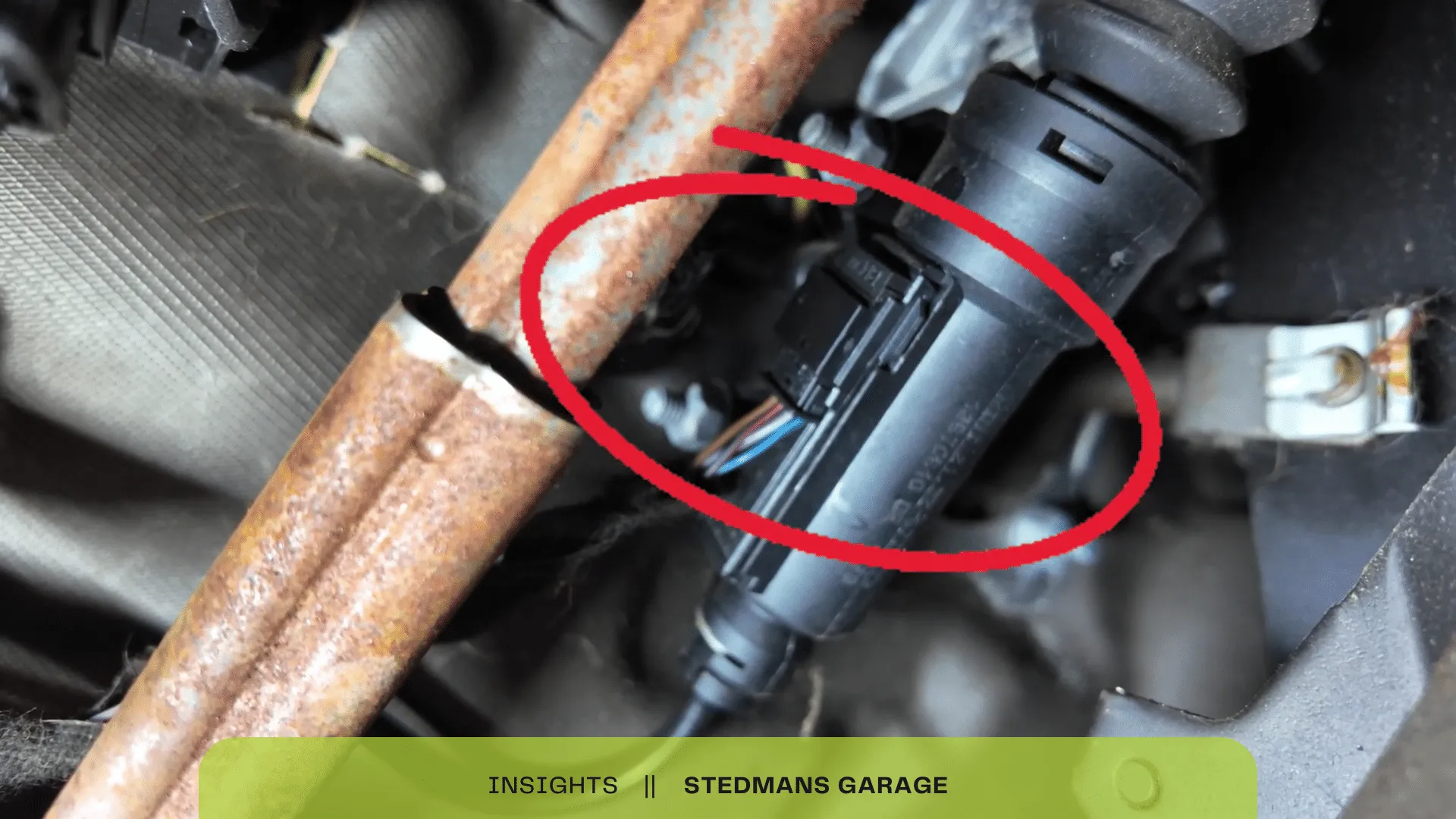
Pin Testing with Multimeter
In the footwell of the Mini Cooper, we located the clutch position sensor attached to the clutch master cylinder. We removed the hall effect sensor to perform wiring checks across all four pins using a multimeter (model number 0W1.8e).
Testing Pin 3
Starting with pin 3, we found that it delivered 14.3 volts, which is a good supply, slightly elevated due to the battery charger being connected.
Testing Pin 2
Next, we reinstalled the clutch position sensor. It’s important to note that the rod passing through the master cylinder, which activates the clutch fluid, is magnetic. The hall effect sensor detects changes in this magnetic field: when the clutch is pressed, the rod moves past the sensor, altering its electrical state.
Observing the multimeter when the clutch pedal was depressed, we noted a voltage change from 0 volts to 12 volts, indicating that the sensor was functioning correctly when engaged.
Verifying ECM Signal
With pin 2 connected to the ECM, we checked the scan tool to confirm if the ECM received this 12-volt signal when the clutch was depressed. In the DME (Digital Motor Electronics), we reviewed the requests and confirmed that a signal of 12 volts was present, indicating proper communication between the sensor and the engine control unit.
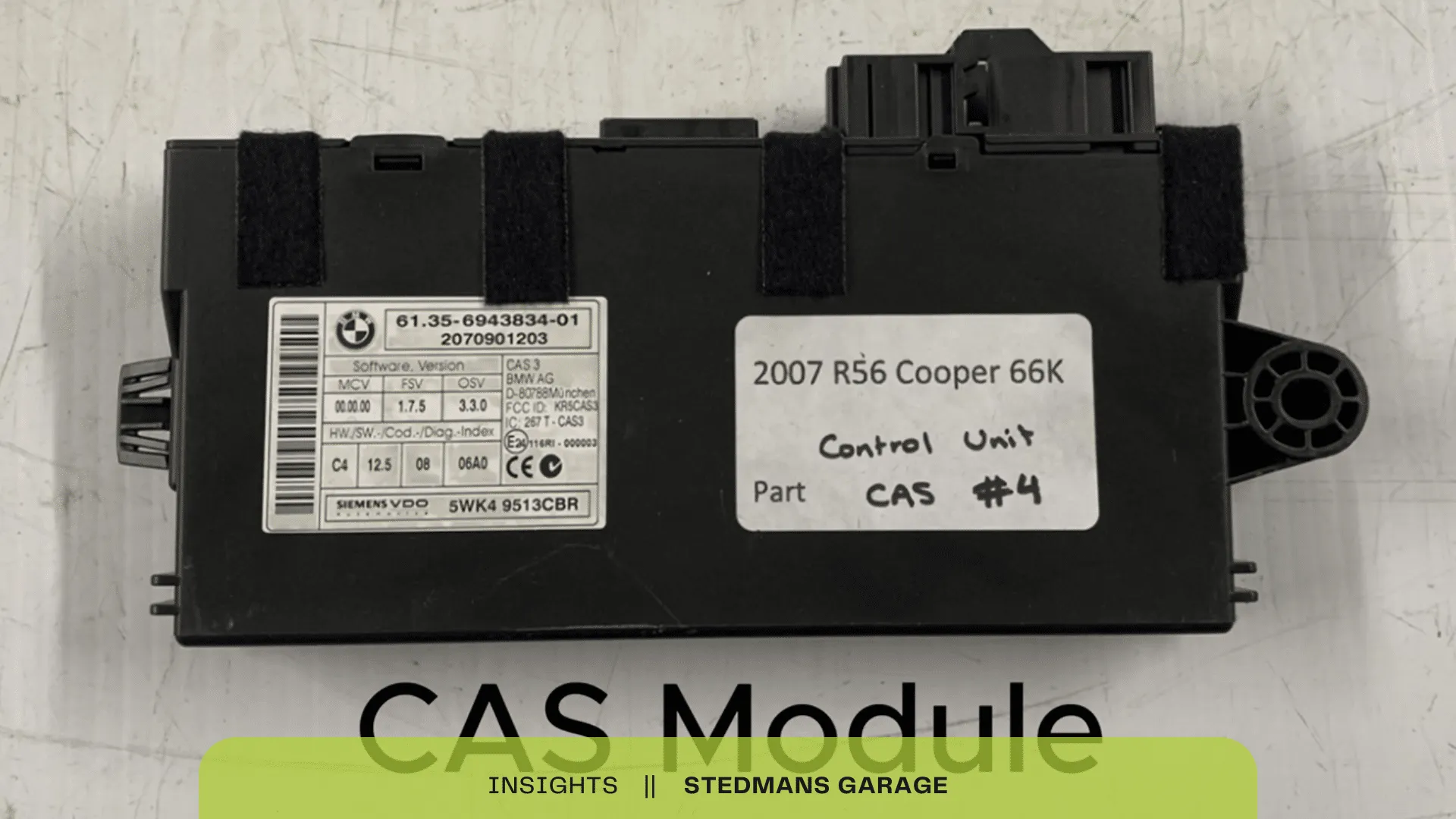
Testing Pin 4
Lastly, we turned our attention to pin 4 and performed another multimeter test. The readings fluctuated between 0 and 0.16 volts, even when the clutch was depressed. This confirmed our suspicion that the issue lay within the clutch position sensor, particularly the signal being sent to the CAS module.
Steps Taken to Fix the Issue
Once we identified the faulty clutch pedal position sensor as the root cause, we proceeded with the following steps to rectify the problem:
- Bypassing the Faulty Sensor: To determine if the issue could be resolved temporarily, we bypassed the faulty clutch position sensor. This allowed us to simulate a functional sensor by sending a signal to the CAS module that the clutch was engaged. This step is crucial for confirming the diagnosis before making any permanent repairs.
- Replacing the Faulty Sensor: After confirming that the bypass worked and the vehicle started correctly, we installed the new sensor and reconnected all wiring according to the manufacturer’s specifications.
- Final Testing: With the new sensor in place, we conducted a final round of tests to ensure that the vehicle could start without issues. We monitored the live data from the CAS module to confirm that the clutch pedal was being correctly detected. This thorough testing ensures the reliability of the repair.
Conclusion: The Root Cause Identified
After extensive testing and analysis, we determined that the issue was a faulty clutch pedal position sensor.
Quick Rundown:
- Confirmed the customer’s complaint.
- Attempted to start the vehicle and noted the clutch pedal prompt.
- Reviewed fault codes and live data.
- Found no signal being sent to the starter motor.
- Analysed the wiring diagram, linking the clutch pedal position sensor to the engine module and CAS module.
- Conducted checks in the footwell with a multimeter at the clutch pedal position sensor.
- Implemented a bypass to simulate the CAS module receiving a request from the faulty sensor.
- Replaced the faulty clutch position sensor and performed final tests.
Result: The vehicle started successfully!
If you experience similar issues with your Mini Cooper or any other vehicle, don’t hesitate to contact us for professional diagnostics and repairs.